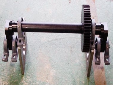
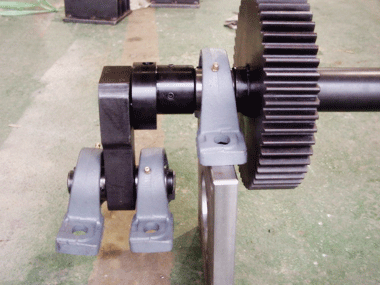
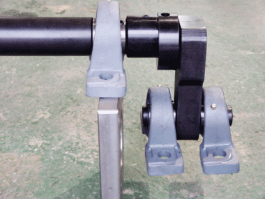
CAM LINK UNIT
It produces more sophisticated products with more advanced technology.
CAM1T
CAM2T
Structure and Performance of the CAM LINK UNIT
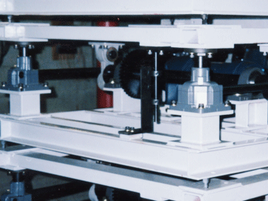
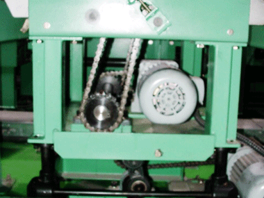
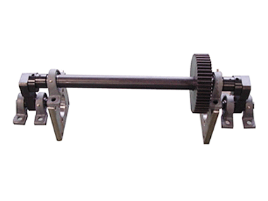
- By connecting a link to the cam and attaching a bracket on top, the rotating cam connected to the bearing shaft converts rotational motion into linear motion, moving the attached bracket up and down. During this process, a unit that serves as a left-right guide is needed, allowing for precise up-and-down movement when combined with the power base.
- Unlike traditional cam mechanisms that are custom-designed by engineers, the CAM LINK UNIT is standardized. It only requires specifying the center distance between the cams, making design easier.
- It can operate smoothly under a nominal load of up to 50% during up/down movements.
- Unlike LM guides, ball bushes, or X-links, the guide is composed of a unit, making maintenance easy and allowing for quick replacement of standardized parts.
Applications of the CAM LINK UNIT
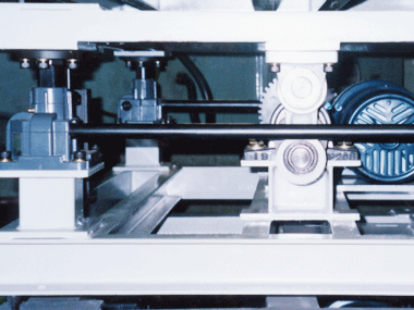
- Diverters for roller and chain conveyors
- Simple up-down lifters requiring strokes of 80mm or less
- Other application devices
Speed Calculation Formula
- Specifications
Load : 180(kgf), Speed : 3(m/min)
- Calculation Formula
(P = POWER(kw), m = Weight(kgf), V = Speed(m/sec), n = Efficiency, g = 9.81)
P = 1750 × 1 / 60 × 15 / 26 × 0.06 × 2
① ② ③ ④ ⑤
= 2.42 (M/Min)
- ① Gear Ratio of Geared Motor
② Number of Sprocket Teeth on the Motor Side (Z)
③ Number of Sprocket Teeth on the CAM LINK Side (Z)
④ Stroke (converted to mm)
⑤ Since the stroke progresses with each half rotation, multiply by 2.
CAM LINK UNIT's Specification
| MODEL |
Drive Source |
Basic Capacity (kgf) |
STROKE (MAX) |
| CAM 10 |
GEARED MOTOR (BREAK TYPE) |
1000 |
60 |
| CAM 20 |
2000 |
60 |
